

Section 1.5: Chips at Radio Frequencies #
The stray inductance and capacitance that troubled the HF amplifier in the previous section can also interfere with signals we want. At UHF and microwave frequencies, a few millimeters of lead between a transistor or chip and its circuit, less than the width of a fingernail, can be enough to hold it back. A useful amplifier needs both a fast enough device and a package that lets it work.
Getting the Leads Out of the Way #
Long pins make a chip easy to handle, plug into a socket, and solder by hand at the kitchen table. In through-hole construction, the pins pass through holes in the circuit board and are soldered on the other side.
Key Information: DIP (dual in-line package) is a through-hole package with two rows of connecting pins on opposite sides of the package.
Those connections have an electrical cost. A signal takes time to travel along a lead. At higher frequencies, the same delay occupies more of a cycle, causing a greater phase shift. Lead inductance matters more too, since its reactance rises with frequency. A package that works well in a controller may be a poor home for a microwave amplifier.
Surface-mount components avoid those long pins. Each part solders directly to pads on the board, and the parts, some smaller than a grain of rice, can sit close together.
Key Information:
- Excessive lead length is why DIP through-hole integrated circuits are not typically used at UHF and higher frequencies.
- Surface-mount packages have the least parasitic effects at frequencies above the HF range.
- At RF, surface-mount technology offers smaller circuit area, shorter board traces, and less parasitic inductance and capacitance than through-hole construction.
Materials That Respond Quickly #
Short connections cannot make up for a device that responds too slowly. A transistor’s gain falls at high frequencies partly because charge can’t move through it instantly. A material’s electron mobility describes how easily electrons move through it when an electric field pushes them. If a silicon device has too little gain at the intended frequency, a semiconductor with higher mobility can support a faster device.
Key Information: Gallium arsenide is used in microwave circuits; its higher electron mobility makes it useful at UHF and higher frequencies.
The “GaAsFET preamp” that many weak-signal VHF and UHF operators mount at the top of the tower is a gallium arsenide FET put to that use.
An MMIC (monolithic microwave integrated circuit) keeps connections shorter still. It forms RF elements together on one semiconductor chip instead of assembling separate parts into a module. Its transistors need a fast semiconductor. Gallium nitride, or GaN, is a compound semiconductor like gallium arsenide. It can also withstand high voltages, which makes it useful for RF power devices. Silicon nitride and silicon dioxide appear on these chips too, but as insulating layers, not as the material that amplifies.
Key Information: Gallium nitride supports the highest frequency of operation when used in MMICs.
A GaN part isn’t automatically faster than every device made from another semiconductor. Check the specific part’s rated frequency range.
An Amplifier as a Building Block #
Many MMICs are ready-made amplifiers, often called gain blocks. The chip already includes much of the transistor biasing and impedance matching, so you don’t have to design an amplifier one transistor at a time.
To be that easy to use, a gain block has to behave predictably. The chip’s design should set its gain, not the parts around it. It should add little noise when the signal is weak. Noise figure measures how much an amplifier degrades the signal-to-noise ratio, so lower is better; Chapter 5 examines it further. Its input and output should match the coax they connect to, usually 50 Ω in amateur radio, at any frequency in its range.
Key Information:
- The most common MMIC input and output impedance is 50 ohms.
- Popular MMIC characteristics include controlled gain, low noise figure, and constant input and output impedance over the specified frequency range.
Connecting and Powering an MMIC #
The external connections still need care. RF has to travel into and out of the chip through a controlled impedance, and the circuit board itself can provide one. Microstrip is a transmission line made from a conducting trace over a ground plane, with insulating board material between them. Trace width, spacing to the plane, and board material help set its impedance.
The amplifier also needs DC power, and the most common gain blocks have no separate supply pin. DC has to share a lead with the RF signal, so the external circuit must sort the two: RF stays out of the supply, and DC stays out of the load.
A resistor sets the bias current. An RF choke passes DC to the amplifier while presenting high impedance to RF, limiting signal loss into the supply branch. A coupling capacitor carries the output signal onward while blocking DC from the load.
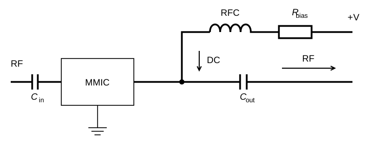
Key Information:
- Microstrip is the type of transmission line often used for connections to MMICs.
- Power is supplied to the most common type of MMIC through a resistor and/or RF choke connected to the amplifier output lead.
Some other MMICs do have a separate supply pin. The next chapter will put numbers to the frequency-dependent behavior that lets inductors and capacitors direct RF and DC along different paths.




 DIP
DIP