

Section 1.7: Timing and Digital Control #
The fan control in the previous section assumed tidy on/off requests. Real sensors are messier. A temperature sensor may produce a voltage that creeps upward with a little noise riding on it, and the controller must turn that into a steady decision.
From Level to Decision #
A comparator compares the sensor’s voltage with a reference voltage that sets the threshold. Its output goes high or low depending on which voltage is greater, giving the logic circuit an on/off state.
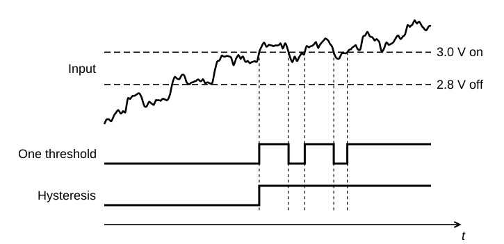
Noise can push an input back and forth across the threshold. The fan controller could keep switching its command on and off at nearly the same temperature. This rapid output switching is called chatter; drive a relay with it, and you can hear where the name comes from.
We can avoid that by using separate thresholds for rising and falling voltage, a behavior called hysteresis. Reversing the output now requires the input to reach the other threshold.
Key Information:
- A comparator changes its output state when its input signal crosses the threshold voltage.
- Hysteresis prevents input noise from causing unstable comparator output signals.
Suppose the command turns on above 3.0 V and turns off below 2.8 V. After it turns on, a fluctuation to 2.95 V leaves it on. The input must fall below 2.8 V to switch it off. That small wobble no longer becomes a new command. A home thermostat uses the same trick so the furnace doesn’t cycle every few seconds. The diagram below feeds the same noisy input to a comparator with one threshold and to one with hysteresis.
Remembering a Bit #
A comparator reacts to its input continuously. Registers and counters need the opposite: they must hold their bits between clock events. A flip-flop has two stable states. Like a wall switch, it stays where you leave it, storing either 0 or 1 until an input or clock event tells it to change.
Key Information: A flip-flop is a bistable circuit.
Dividing and Counting #
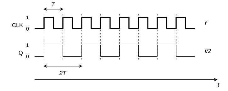
That stored state also lets us divide a clock frequency. The circuit responds to a selected clock edge: a low-to-high or high-to-low transition.
Arrange a flip-flop to toggle, or change to the opposite state, at each rising clock edge. One pulse takes the output from 0 to 1; the next takes it back to 0. Two input periods make one complete output cycle. The falling edges leave its state alone.
Key Information: A flip-flop can divide the frequency of a pulse train by two.
For a still slower signal, connect toggling stages in a chain, each one driven by the output of the one before. With a 16 kHz input, successive stages give 8 kHz, 4 kHz, 2 kHz, and finally 1 kHz. For stages, the division factor is .
Repeated halving cannot give us every useful count. To count in tens, a decade counter advances through ten states before repeating.
Key Information:
- Four flip-flops are required to divide a signal frequency by 16.
- A decade counter produces one output pulse for every ten input pulses.
Several decade counters in a row can divide by 100 or 1000. A frequency counter uses such dividers to set a precisely timed interval from a crystal clock, then counts input cycles during that interval. With a one-second interval, the count is the frequency in hertz.
Stable and Timed States #
A brief trigger may need to produce a longer pulse—for example, to keep an indicator lit long enough to see. A monostable circuit has one stable resting state. Also called a one-shot, it turns the trigger into a pulse of a chosen duration.
To advance a counter at regular intervals, we need a repeating clock. An astable circuit can supply one. It has no stable resting state, so its timing network never lets it settle.
These circuits belong to a family called multivibrators. Their names count the stable states: “bi-” means two, “mono-” means one, and “a-” means none.
Key Information:
- A monostable multivibrator switches temporarily to an alternate state for a set time.
- An astable multivibrator continuously alternates between two states without an external clock signal.
Configuring a Larger Circuit #
Combining many gates, stored bits, and counters could mean wiring together a lot of separate chips. A field-programmable gate array, or FPGA, puts many logic resources and configurable connections on one chip. Its configuration determines how those resources work together as gates, registers that store groups of bits, counters, and other circuits. A designer describes the hardware’s behavior and connections in a special language. Design tools translate that description into a configuration for the chip.
Key Information: A hardware description language, or HDL, is used to design an FPGA’s configuration.
The resulting circuit gives each task its own hardware, so one counter can count pulses while other logic handles a different signal, all at once. No processor has to step through the operations in sequence. That speed is why many SDR transceivers use an FPGA to keep up with their receivers’ data.




 The comparator changes its output state