

Section 2.1: Phase and Stored Energy #
Switch off a power supply, and its filter capacitors can hold a dangerous charge until a bleeder resistor drains them. The draining isn’t instant. The stored energy leaves only as current flows through the resistor, and the resistor limits that current. Storing and returning energy takes time in AC circuits too, where it makes voltage and current peak at different times.
Charging Takes Time #
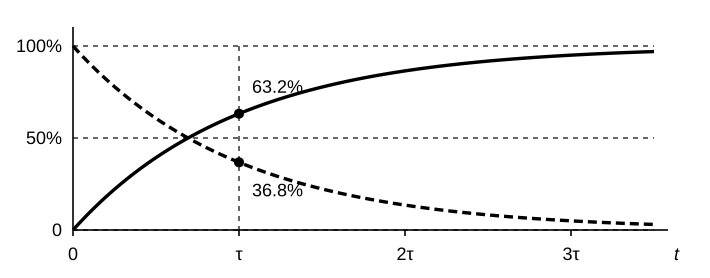
Connect an uncharged capacitor to a DC source through a resistor, and it charges quickly at first. As capacitor voltage rises toward the source voltage, less voltage remains across the resistor. That reduces current, so each further increase takes longer. The voltage curves toward its final value.
The resistor and capacitor set the pace together. Multiply resistance by capacitance to find the circuit’s time constant:
The symbol is the Greek letter tau. Here is resistance in ohms and is capacitance in farads; the result is seconds. One time constant is a checkpoint, not the finish line.
Key Information: One time constant is the time needed for a capacitor to charge to 63.2% of the applied voltage, or discharge to 36.8% of its initial voltage.
For example, a capacitor charging from zero toward 10 V reaches 6.32 V after one time constant. It still has 3.68 V to go. During the next interval, it gains 63.2% of that smaller gap: about 2.33 V, bringing it to 8.65 V. The charging slows as the gap shrinks.
Discharging follows the reverse pattern. A capacitor starting at 10 V falls to 3.68 V after one time constant, and the next interval leaves 36.8% of that, about 1.35 V.
A bleeder circuit shows the time constant at work. Suppose a power supply has two 220 µF filter capacitors connected in parallel, with a 1 MΩ bleeder resistor across each one. All four parts are then in parallel, and once you switch the supply off, the capacitors discharge through the resistors. Before multiplying, treat each parallel pair as one component:
- Two equal resistors in parallel have half the resistance of one: two 1 MΩ resistors give 0.5 MΩ.
- Parallel capacitors add: two 220 µF capacitors give 440 µF.
A megohm is a million ohms ( Ω), and a microfarad is a millionth of a farad ( F). Those factors cancel when we multiply, so we can use the numbers as written:
Key Information: Two 220-microfarad capacitors and two 1-megohm resistors, all in parallel, have a time constant of 220 seconds.
That’s a little under four minutes, and more than a third of the starting voltage remains. A high-voltage supply can stay dangerous well past one time constant.
A Waveform Is a History #
With an AC source, a capacitor never settles. It charges, discharges, and charges the other way, cycle after cycle. The charging curves above plot voltage against time. The same kind of graph can follow an AC signal, with time along the horizontal axis and voltage or current on the vertical axis. A taller trace means greater amplitude; a shorter interval between cycles means higher frequency. A spectrum display instead plots amplitude against frequency.
Key Information: A signal in the time domain shows its amplitude at different times.
One complete cycle spans 360 degrees of phase. A quarter-cycle spans 90 degrees. If one wave reaches each corresponding peak or zero crossing before another wave, it leads; the later wave lags. Follow the graph from left to right: the wave that gets to a matching peak first is the one that leads.
Where the Energy Goes #
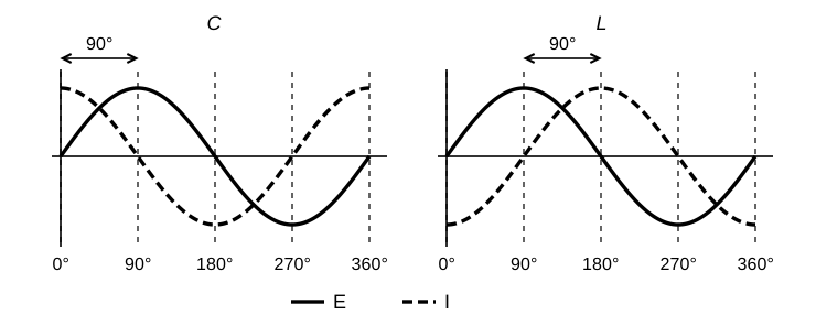
A resistor’s current rises and falls with its voltage as it turns electrical energy into heat. A capacitor stores energy in an electric field between its plates, so current must first move charge onto those plates to change the voltage. With a sine-wave voltage, current is greatest while voltage is changing fastest, just as it was at the start of the charging curve. Current is zero at the voltage peak, where the voltage momentarily stops changing. The fastest change comes as the voltage rises through zero, a quarter-cycle before its peak.
An inductor stores energy in a magnetic field around its winding. Changing its current requires voltage, and the faster the current changes, the more voltage it takes. The voltage peaks while the current is changing fastest, as the current rises through zero.
Key Information:
- In an ideal capacitor, AC current leads voltage by 90 degrees.
- In an ideal inductor, AC voltage leads current by 90 degrees.
The graphs below mark progress through one cycle in degrees.
These are steady sine-wave relationships for ideal components. Reactance, measured in ohms, describes the opposition capacitors and inductors present to AC by storing energy. Real coils and capacitors also have some loss, which we will account for later in this chapter.
Real and Reactive Power #
The current through a coil does not by itself tell us how many watts it consumes. Energy enters its magnetic field during part of the AC cycle and returns to the circuit during another part. A capacitor does the same with its electric field. In ideal components, those amounts balance. Power that flows in and back out this way each cycle is called reactive power.
Key Information:
- In ideal inductors and capacitors, energy is stored in magnetic or electric fields, but power is not dissipated.
- For reactive power, current and voltage are 90 degrees out of phase.
- Reactive power is called wattless, nonproductive power.
“Nonproductive” is a rather unflattering name for something a radio depends on. Storing energy and giving it back is exactly what we need for tuning and filtering. We measure reactive power in volt-amperes reactive, or VAR, and real power in watts.
Suppose 1 A RMS flows through a 100 Ω resistor and an ideal 100 Ω inductive reactance in series. Both carry the same current, but only the resistor turns energy into heat. Use with the resistance, leaving the reactance out of the heat calculation:
Key Information: A circuit consisting of a 100-ohm resistor in series with a 100-ohm inductive reactance drawing 1 ampere consumes 100 watts of real power.
The inductor still affects how much voltage the source must supply. Finding that voltage requires a way to keep resistance and reactance separate while combining their effects.




 One time constant