

Section 2.3: Calculating AC Circuits #
The impedance triangle has given us one number so far: the magnitude. Its angle completes the description, telling how far voltage and current are out of step. One more calculator function finds it, and a little care with signs keeps it pointing the right way once an inductor and a capacitor share a circuit.
An Angle from the Triangle #
In the impedance triangle, the vertical side divided by the horizontal side, , is the tangent of the angle. A calculator’s inverse tangent function works backward: give it that ratio and it finds the angle. Written as a formula for the phase angle (phi),
Look for
or atan on your calculator, often through a shift or second-function key. Here the
means inverse tangent, not “1 divided by tangent.” Set the calculator to degrees, the unit used for these angles. As a check,
should give 45°; a result near 0.785 means it’s set to radians, a classic exam-day trap.
The previous section’s triangle gives . With the 500 Ω magnitude we already found, its polar form is 500 Ω at +53.1°.
This angle describes voltage relative to current. A positive angle means voltage leads; a negative angle means voltage lags. The +53.1° load is inductive, and its voltage leads, just as an inductor’s does.
Net Reactance Sets the Angle #
Put an inductor and a capacitor in series, and their reactances play tug-of-war with the impedance point, one pulling up and one pulling down. Find where that leaves the point before calculating its angle; adding both reactance magnitudes would put it in the wrong place.
A series RLC circuit contains resistance , inductance , and capacitance . Its net reactance is
Positive means the circuit is inductive overall; negative means it is capacitive. That net value becomes the vertical side of the triangle.
Take , , and , or 1000 Ω:
- Subtract the reactances:
- Divide by resistance:
- Find the angle:
The figure below draws this example on the impedance graph.
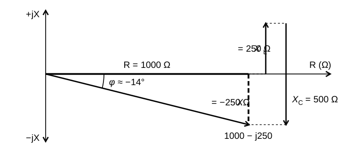
The capacitor has the larger reactance, so we expected a capacitive result: voltage lags, as the minus sign says. You can check the angle’s size too. Ignoring signs, a net reactance smaller than the resistance gives an angle under 45°, and a larger one gives an angle over 45°. Both checks catch calculator slips.
Two more circuits use the same steps. With and , net reactance is −200 Ω. Dividing by the 100 Ω resistance gives −2; inverse tangent gives about −63.4 degrees.
With and , net reactance is +50 Ω. The resistance is again 100 Ω, so the ratio is +0.5 and the angle is about +26.6 degrees.
Key Information: In a series RLC circuit:
- With , , and , the voltage lags the current by 14.0 degrees.
- With , , and , the voltage lags the current by 63 degrees.
- With , , and , the voltage leads the current by 27 degrees.
Turning the Ratio Over #
Every part of a series circuit carries the same current. Parallel branches share the same voltage instead, and their currents add. Working with current per volt makes those branches easier to combine: we can add their admittances. Impedance is voltage over current, . Admittance flips that ratio to current over voltage, , and is measured in siemens, abbreviated S. For a 50 Ω resistor, divide 1 by 50 to get 0.02 S. Apply 1 V and it passes 0.02 A.
Like impedance, admittance has two perpendicular components:
The real part, , is called conductance.
Key Information:
- Admittance is the inverse of impedance: .
- Susceptance is the imaginary part of admittance and is commonly represented by the letter .
In “inverse of impedance,” inverse means the reciprocal, 1 divided by the impedance, not the inverse-tangent sense used earlier. An impedance given in polar form has both a magnitude and an angle to convert. For an impedance of at :
- Divide 1 by 100: the admittance magnitude is 0.01 S.
- Reverse the sign of +30°: the admittance angle is −30°.
Both changes come from flipping the ratio: the size relationship reverses, and so does which quantity leads.
A pure inductive reactance of has an admittance of . The magnitude becomes , and the angle changes from to . With no resistance, all of that admittance is susceptance. The magnitude is always positive; the sign belongs to the phase angle.
Key Information:
- Converting the magnitude of pure reactance to susceptance replaces it with its reciprocal.
- To convert polar impedance to admittance, take the reciprocal of the magnitude and change the sign of the angle.




 14.0 degrees with the voltage lagging the current