

Section 3.1: Filters and Matching Networks #
A transmitter’s signal often passes through two networks on its way to the antenna. A low-pass filter keeps harmonics off the air, and a matching network, such as an antenna tuner, gives the transmitter the load it was designed for. Both rely on inductors and capacitors, and one network can often do both jobs.
Matching While Filtering #
A transmitter usually expects a 50 Ω resistance, but an antenna system may present something like . That load has two problems: 30 Ω of reactance that shouldn’t be there, and 25 Ω of resistance where 50 Ω belongs.
Key Information: An impedance-matching circuit transforms a complex impedance to a resistive impedance by canceling the reactive part and changing the resistive part to the desired value.
Ideally, inductors and capacitors do this without wasting power, since they store energy and return it each cycle. Their reactances change with frequency, though, so the network also passes some frequencies more easily than others. That lets a matching network filter.
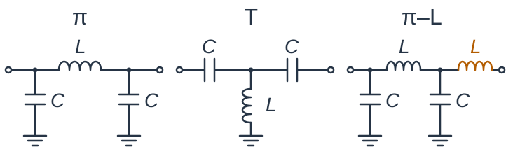
The Pi-network, long used in tube amplifier output circuits, is one example. Its schematic looks like the Greek letter , as the left drawing in the figure below shows: two legs run down to ground, joined across the top. Parts in the legs are shunt elements, connected from the signal path to ground; the part across the top is a series element.
Key Information: A low-pass Pi-network has a capacitor between the input and ground, another capacitor between the output and ground, and an inductor between the input and output.
As frequency rises, the series inductor’s reactance grows while the shunt capacitors’ reactance falls. The path toward the load gets harder and the path to ground gets easier, so less high-frequency signal reaches the load.
A T-network has two series arms and a shunt branch to ground where they meet. With capacitors in the series arms and an inductor in the shunt branch, the trend reverses: low frequencies face large series reactance and an easy path to ground. Many antenna tuners use this T.
A low-pass network can pass a 7 MHz signal while weakening its harmonics at 14 and 21 MHz. When a Pi-network alone doesn’t weaken them enough, another series inductor can follow it at the output. That inductor’s reactance is three times as large at 21 MHz as at 7 MHz.
Key Information:
- A T-network with series capacitors and a shunt inductor has a high-pass frequency response.
- A Pi-L network is a Pi-network with an additional output series inductor. Adding that inductor provides greater harmonic suppression.
Reading the Response #
How much a network weakens its harmonics shows on a graph of its frequency response. Its vertical scale reads in decibels, where each 10 dB step is another factor of ten in power. Equal steps multiply power rather than add to it: from −20 to −40 dB, power falls to one-hundredth. That spacing lets one graph show a passband near 0 dB beside rejection 60 dB or more below it.
Key Information: Circuit frequency-response graphs most often use a logarithmic Y-axis scale.
Above a low-pass filter’s cutoff frequency, where output is down 3 dB, the response falls through a transition into the stopband, the range the filter rejects. Harmonics sit far above the signal, so a gradual transition can be enough for them. A receiver filter may need to reject a strong signal just outside its passband, which calls for much steeper sides.
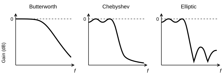
Steepness usually comes at a price: ripple, a rise and fall of the response within a band. A Butterworth response keeps the passband flat, at the cost of a gentler fall. Allowing some passband ripple buys a sharper cutoff. Some designs go further and place notches in the stopband, narrow ranges of especially strong rejection that show as deep dips on the graph. A notch just beyond the passband pulls the response down even faster.
Key Information:
- A Chebyshev filter has ripple in the passband and a sharp cutoff.
- An elliptic filter has an extremely sharp cutoff with one or more notches in the stop band.
Shape factor puts a number on steepness. It compares a filter’s bandwidths at two attenuation levels, commonly the bandwidth 60 dB down divided by the bandwidth 6 dB down. A ratio closer to one means steeper sides. For example, a filter 3 kHz wide at 6 dB down and 6 kHz wide at 60 dB down has a shape factor of .
Key Information: Shape factor measures a filter’s ability to reject signals in adjacent channels.
Choosing a Resonator #
A narrow passband with steep sides takes high-Q resonators, and the right kind depends on frequency and power. Quartz crystals give a very sharp resonance but can safely handle only a little signal power, so crystal filters work where signals are weak, such as in a receiver’s IF stages. One classic design wires its crystals in a criss-cross bridge pattern called a lattice; the name describes that wiring, not the crystals’ shape.
At VHF and UHF, a helical resonator, a coil inside a conducting can, packs high Q into a space small enough to fit inside a radio.
A 2-meter repeater receives and transmits at the same time on frequencies only 600 kHz apart. Its receiver listens for signals more than a trillion times weaker than its own transmitter’s output. Its duplexer lets the transmitter and receiver share one antenna while keeping the transmitter’s power out of the receiver. Cavity filters, resonant chambers of conducting metal, provide the very high Q and power handling this job requires.
Key Information:
- A crystal lattice filter is a filter for low-level signals made using quartz crystals.
- A helical filter is most frequently used as a band-pass or notch filter in VHF and UHF transceivers.
- A 2-meter band repeater duplexer uses cavity filters.




 It cancels the reactive part of the impedance and changes the resistive part to the desired value