Section 3.4: Regulated Power Supplies #
Run an SSB transmitter from an unregulated supply, and the supply’s output sags on every voice peak, then climbs back when you pause. Filtering smooths the ripple, but a regulator holds the output steady as the input voltage and load current change.
Continuous Control #
Holding an output steady takes a fixed voltage to compare it with and a part that can correct it. The Zener diode from Chapter 1 holds a nearly constant voltage as its current varies. A transistor, conducting more or less as needed, can make the correction.
Key Information:
- A linear electronic voltage regulator works by varying the conduction of a control element to maintain a constant output voltage.
- A Zener diode is used as a stable voltage reference.
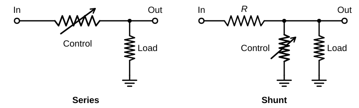
A series regulator puts its control element in the path between source and load. The common three-terminal regulator chip packs this kind of control element and a reference into one small package.
A shunt regulator puts its control element across the output, in parallel with the load. A resistor in series with the source carries both the load current and the shunt current. When the output starts to rise, the shunt element draws more current, the drop across the series resistor grows, and the output comes back down. A Zener diode with a series resistor is the simplest example.
Key Information:
- A three-terminal voltage regulator is a series regulator.
- A shunt regulator is the type of linear voltage regulator that operates by loading the unregulated voltage source.
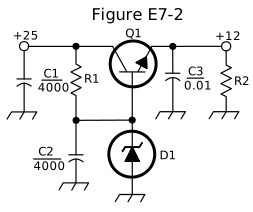
Figure E7-2 builds a series regulator from separate parts.
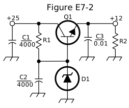
Q1, an NPN transistor between the +25 V input and the +12 V output, is the control element, or pass transistor: all the load current passes through it. R1 feeds current to D1 and Q1’s base, and D1 holds the base steady. As in an emitter follower, the output at Q1’s emitter stays about one base-emitter drop lower. If the output sags, Q1’s base-to-emitter voltage rises, so Q1 conducts more and restores it. Many regulators also have an amplifier that compares the output with the reference, a feedback loop this simple circuit lacks.
The +25 V input comes from a rectifier, and even after C1 it carries some ripple that R1 would pass to the reference. C2 is as large as C1, but it isn’t an output filter. It sits across D1, giving that ripple an easy path to ground and keeping the base voltage smooth.
Key Information:
- The circuit shown in Figure E7-2 is a linear voltage regulator.
- In Figure E7-2, the purpose of Q1 is to control the current to keep the output voltage constant.
- In Figure E7-2, the purpose of C2 is to bypass rectifier output ripple around D1.
Headroom and Heat #
A series regulator can only take voltage away, and its control element needs some voltage across it to keep control. If the input falls too close to the output, the regulator runs out of room to correct. A regulator that needs 2 V of room must have at least 14 V in to provide 12 V out, even at the lowest dips of the input ripple.
The voltage the regulator takes away becomes heat, because the full output current flows through the control element across that difference. The control element dissipates
Running the regulator itself takes a little more. If Figure E7-2 supplies 1 A, Q1 dissipates . That’s more than the 12 W the load receives, so the regulator ends up as the hottest part in the box.
Key Information:
- The dropout voltage of a linear voltage regulator is the minimum input-to-output voltage required to maintain regulation.
- The power dissipated by a series linear voltage regulator is the voltage difference from input to output multiplied by the output current.
Controlling Pulses Instead #
A switchmode regulator avoids most of that heat. It turns its control element fully on and off instead of holding it partly on. As with the switching amplifiers earlier in this chapter, the element rarely has large voltage and large current at once.
A filter that stores energy turns the resulting pulses into a steady output. Duty cycle is the fraction of each switching period spent on. If each period lasts 10 µs, staying on for 2 µs gives a duty cycle of , or 20%; 5 µs gives 50%. More on-time sends more energy to the output, so the controller lengthens it when the output sags and shortens it when the output rises.
Key Information: A switchmode voltage regulator works by varying the duty cycle of pulses input to a filter.
Many switching supplies rectify the AC line to DC first. An inverter then chops that DC into AC at tens of kilohertz or more, far above the 60 Hz of a linear supply’s transformer. At that frequency, a transformer moves a smaller packet of energy on each cycle, many more times per second, and the filters need only bridge the short gaps between packets.
Key Information: A switching type power supply is less expensive and lighter than an equivalent linear power supply because its high-frequency inverter design uses much smaller transformers and filter components for an equivalent power output.
Fast switching can also cause interference, as Section 9.3 explains.
Stored Energy at Higher Voltage #
Bleeder resistors drain a supply’s filter capacitors after it turns off. In a high-voltage supply, they take on extra jobs. Such a supply may stack several filter capacitors in series to get enough voltage rating. Their leakage currents differ, so equal capacitance alone doesn’t make the voltage divide equally. Equal resistors across the capacitors draw enough current to swamp those differences, and that current flows even with nothing connected to the output.
At switch-on, uncharged capacitors can draw a huge current. A step-start circuit feeds them through a current-limiting resistor at first, then bypasses it.
Key Information:
- Connecting equal-value resistors across series-connected power supply filter capacitors equalizes the voltage across each capacitor, discharges the capacitors when voltage is removed, and provides a minimum load on the supply.
- A step-start circuit in a high-voltage power supply allows the filter capacitors to charge gradually.
Discharge takes time, and a resistor can fail, so bleeders don’t prove that a capacitor is safe. High-voltage supply work requires training and equipment for handling stored energy safely.




 The conduction of a control element is varied to maintain a constant output voltage