

Section 5.2: Digital Signal Processing #
A receiver that samples everything from near DC to 30 MHz captures the whole HF spectrum at once, as tens of millions of numbers every second. To hear one SSB voice, though, you need only about 3 kHz of it. Digital processing has to pick out that channel and drop the data it doesn’t need. Its tools are simple: delaying samples, scaling them, and adding them. The same tools can also generate a signal for transmitting.
Frequency and Sample Rate #
That wide capture lets an SDR show the whole band on a spectrum or waterfall display. To draw one, the radio must measure how strong each frequency is across a block of samples. A record of amplitude against time is the time-domain view of a signal; strength against frequency is the frequency-domain view. The fast Fourier transform, or FFT, is a quick way to do the Fourier analysis from Section 4.1 on such a block. It doesn’t convert between analog and digital; the samples must already exist.
Key Information: A Fast Fourier Transform converts signals from the time domain to the frequency domain.
Hearing one channel takes far less data than drawing the band. Once the receiver has chosen a narrow channel, it doesn’t need every sample. Suppose earlier stages have already narrowed the stream to 48,000 samples per second. Keeping one sample in four cuts that to 12,000. That also lowers the Nyquist limit from 24 kHz to 6 kHz. A component at 8 kHz would now alias to 4 kHz ( ) and could pass for a wanted signal.
Key Information:
- The function of decimation is reducing the effective sample rate by removing samples.
- A decimator requires an anti-aliasing filter because the filter removes high-frequency signal components that would otherwise be reproduced as lower frequency components.
Taps and Filter Shape #
To pass some frequencies and reject others, a digital filter combines samples taken at different times. Picture a line of stored samples, newest at one end; each step back is one sample interval earlier. The filter multiplies those values by chosen weights and adds the results. Each point where it reads a stored sample is called a tap.
For a small example, average the current sample with the preceding one. Steady samples of 1 and 1 give : the steady signal passes. Alternating samples of 1 and give zero: this rapid variation cancels. Different weights produce more useful frequency responses. At the same sample rate, more taps lengthen the time span the filter compares, so it can tell apart closer frequencies.
Key Information:
- Taps in a digital signal processing filter provide incremental signal delays for filter algorithms.
- More taps allow a digital signal processing filter to create a sharper filter response.
A finite impulse response, or FIR, filter uses a finite set of these weighted samples. Feed it one isolated pulse, and once that pulse has passed the last tap, the output returns to zero. If its weights are symmetrical about the middle tap, every frequency component emerges centered on that tap, half the filter’s length later. Their relative timing stays intact, which helps preserve the waveform’s shape. The trade-off is work: compared with filters that feed their output back into the calculation, an FIR filter usually needs more taps, more calculation, and more delay for the same steep rolloff.
A fixed FIR filter keeps the same response until its weights change. An adaptive filter adjusts its weights continually to suit the input. Speech has patterns that repeat over short spans, and random noise doesn’t, so such a filter can keep adjusting to pass what it can predict.
Key Information:
- FIR filters can delay all frequency components of the signal by the same amount.
- An adaptive DSP audio filter is used to remove unwanted noise from a received SSB signal.
Quadrature Makes a Sideband #
Section 4.1 built SSB from a balanced modulator and a sharp filter that removes one sideband. DSP can instead cancel the unwanted sideband. It splits the audio into two paths, 90 degrees apart at every audio frequency. A Hilbert-transform filter provides that quadrature path, while the original path passes through a matching delay.
The two paths then modulate the I and Q carriers from Section 4.3, which are also 90 degrees apart. Added together, the two results reinforce one sideband and cancel the other. Subtracting them instead keeps the opposite sideband.
Key Information:
- One method of generating an SSB signal using digital signal processing combines signals in quadrature phase relationship.
- A Hilbert-transform filter is the type of DSP filter used to generate an SSB signal.
Synthesizing an Oscillator #
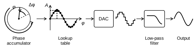
The PLL in Section 3.5 reaches a chosen frequency by steering an analog oscillator. Direct digital synthesis (DDS) computes the waveform instead, one value per tick of a fixed clock. A phase accumulator tracks the position within the cycle. On each tick it advances by a chosen increment, then wraps around after a full cycle. A larger increment completes cycles faster, producing a higher frequency.
The phase value selects an entry in a lookup table. For a sine wave, the entries at 0, 90, 180, and 270 degrees are proportional to 0, +1, 0, and −1, whatever frequency the synthesizer generates. A DAC turns those numbers into voltage steps, and a low-pass filter smooths them, as in the previous section. DDS designers often call this filter an anti-alias filter, though it does the same smoothing.
Rounding phase or amplitude values leaves small errors. The accumulator’s pattern of steps repeats over and over, so the errors repeat too. Like the quantization tones from an ADC, repeating errors pile up at a few frequencies rather than spreading out as broadband noise. Engineers call the resulting tones spurs. Flaws in the DAC can add more.
Key Information:
- A direct digital synthesizer uses a phase accumulator, lookup table, digital-to-analog converter, and a low-pass anti-alias filter.
- The lookup table of a direct digital synthesizer contains amplitude values that represent the desired waveform.
- The major spectral impurity components of direct digital synthesizers are spurious signals at discrete frequencies.




 Converting signals from the time domain to the frequency domain