

Section 5.4: Receiver Limits and Distortion #
A receiver can hear an extremely weak test signal and still struggle on a crowded band. Nearby strong signals place different demands on its filters, amplifiers, mixers, and converter. Some interference enters through the antenna; some is created inside the receiver itself.
The Other Frequency That Fits #
A superheterodyne receiver’s mixer converts two input frequencies to the same IF: the wanted signal and an image twice the IF away. Once the image reaches the IF, even a sharp IF filter can’t separate it, so the input circuits must reject it before the mixer. With a 455 kHz IF, the image of a 14.000 MHz signal is only 0.91 MHz away, too close for a broad input filter to remove. With a 9 MHz IF, it is 18 MHz away.
Key Information: A high IF makes it easier for a superheterodyne receiver’s front-end circuitry to eliminate image responses.
Products That Were Never Transmitted #
Image rejection does nothing about signals the receiver makes itself. If a stage’s output isn’t strictly proportional to its input, the stage effectively multiplies together the signals passing through it. That creates new frequencies, called intermodulation products. Ideally, a mixer mixes each signal with the LO alone. Strong signals also mix with each other and with LO harmonics.
Two signals at frequencies and can produce third-order products at and . For example, signals at 14.020 and 14.030 MHz produce products at 14.010 and 14.040 MHz, right beside the real stations. Their second-order sum and difference land far outside the band, at 28.050 MHz and 10 kHz, where later filtering rejects them. Fifth-order products, such as MHz, land close by too.
Key Information:
- When the input signal levels to a mixer are too high, spurious mixer products are generated.
- Nonlinear circuits or devices cause intermodulation.
- Odd-order intermodulation products are of particular interest because odd-order products of two signals in the band being received are also likely to be within the band.
Third-order products also grow faster than the signals that make them. In a two-tone test, raising both test signals by 1 dB raises each third-order product by about 3 dB. The products gain 2 dB on the signals with each step, so on a graph the two straight-line trends must eventually cross. That crossing is the third-order intercept point, and the input level there is the input intercept, . The real receiver overloads first, so the point exists only on the extended lines. It isn’t a safe input level or a threshold below which intermodulation disappears. A higher intercept raises the signal level at which intermodulation becomes a problem.
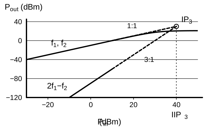
Key Information: A third-order intercept level of 40 dBm means a pair of 40 dBm input signals will theoretically generate a third-order intermodulation product with the same output amplitude as either input signal.
The 3-to-1 slope also explains the receive attenuator from the chapter introduction. Each 1 dB of attenuation lowers the wanted signal 1 dB but third-order products about 3 dB.
Compression and Lost Sensitivity #
A receiver’s dynamic range runs from the weakest signal it can detect to the strongest it can handle without serious distortion. At the top, its amplifiers run out of room. Near its limit, an amplifier’s output stops keeping pace with its input and the gain compresses, as the blue curve in the graph above bends. At the 1 dB compression point, output falls 1 dB short of the straight-line trend. A strong unwanted signal can push a stage into compression, so it amplifies the weak wanted signal less too. You hear the weak station fade whenever the strong neighbor transmits.
Blocking dynamic range measures the room before this happens. If the noise floor is dBm and a dBm test signal causes 1 dB of compression, blocking dynamic range is dB.
A stage that isn’t linear can also copy a strong signal’s modulation onto other signals. The neighbor’s speech then rides along on another station. This is cross modulation.
A roofing filter limits bandwidth early in the IF chain to protect the stages after it. It weakens signals a few kilohertz away before they reach the later amplifiers and mixers, so they must be much stronger to compress those stages. The filter can’t undo overload ahead of it. If a narrower final filter already sets the noise bandwidth, the roofing filter adds protection from strong signals, not a lower noise floor.
Key Information:
- The reduction in receiver sensitivity caused by a strong signal near the received frequency is desensitization.
- The blocking dynamic range of a receiver is the difference in dB between the noise floor and the level of an incoming signal that will cause 1 dB of gain compression.
- Poor dynamic range in a receiver causes spurious signals from cross modulation and desensitization from strong adjacent signals.
- A narrow-band roofing filter improves blocking dynamic range by attenuating strong signals near the receive frequency.
A direct-sampling radio has no narrow roofing filter ahead of its converter, so its ADC sees the sum of every signal in its input bandwidth. A strong broadcast station far from your frequency still adds to that total. The ADC has no code for a voltage beyond its full-scale range, so it flattens, or clips, peaks past that point. The distortion spreads across the whole sampled spectrum. Reaching the maximum code is the symptom, not the limit; storage and sampling speed play no part.
Key Information: An SDR receiver is overloaded when input signals exceed the reference voltage of the analog-to-digital converter.
Oscillator Noise #
Sometimes the background noise rises only while a strong signal is nearby, even though the filter keeps that signal out. The cause can be the receiver’s own local oscillator. Small, rapid wobbles in an LO’s phase spread a little noise, called phase noise, on either side of its frequency. These wobbles differ from a slow drift in tuning.
The mixer uses that same LO for every signal it converts. The strong neighbor comes out beside the IF passband, carrying a copy of the LO’s noise skirt. Part of that skirt lands inside the wanted passband, raising the background there.
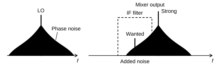
In a direct-sampling SDR, the master clock times every ADC sample, so it plays the LO’s role. Phase noise on that clock acts just as LO phase noise does, and digital filtering can’t remove the result.
Key Information:
- Reciprocal mixing is local oscillator phase noise mixing with adjacent strong signals to create interference to desired signals.
- Excessive phase noise in an SDR receiver’s master clock oscillator can combine with strong signals on nearby frequencies to generate interference.




 Easier for front-end circuitry to eliminate image responses