

Section 6.4: Wire Antennas and Ground #
The common rule cuts a dipole about 5% short of a free-space half wave, because a wire’s thickness makes it act electrically longer, as Section 2.5 showed. Feed that dipole at its center and it presents roughly 73 Ω. Feed the same wire at an end and it presents thousands of ohms, because current is highest at the center and voltage is highest at the ends. Many wire antennas reshape that dipole to get a different impedance, more bands, or a different pattern.
Variations on the Dipole #
The folded dipole keeps an ordinary dipole’s half-wave span but adds wire, as the figure shows. It is not a dipole with its tips bent downward.
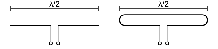
The feed connects at the center of one wire. With two equal-sized, closely spaced wires, the antenna current divides equally between them, so the feed point carries only half the total. Delivering the same power with half the current takes four times the resistance, since , and .
Key Information:
- A folded dipole antenna is a half-wave dipole with an additional parallel wire connecting its two ends.
- The approximate feed point impedance at the center of a two-wire half-wave folded dipole antenna is 300 ohms.
Moving the feed point changes the impedance too. On the second harmonic, the wire holds two half-waves, and its center becomes a voltage peak, so a center feed sees thousands of ohms. At a point about a third of the way from one end, the impedance stays moderate on several bands, and one matching transformer can then serve all of them. Feeding off center does not make the antenna resonant everywhere or keep current off the coax shield.
Key Information: The purpose of feeding an off-center-fed dipole (OCFD) between the center and one end instead of at the midpoint is to create a similar feed point impedance on multiple bands.
The Feed Section #
A section of feed line can also do the matching, as the previous section showed. The G5RV relies on that. The open-wire line feeding its center transforms impedance, so the line’s length is part of the antenna design; swapping in a convenient scrap of line changes the match. A balun then joins the balanced line to unbalanced coax.
Open-wire line also feeds the Zepp, but at one end of the wire instead of the center. A quarter-wave section of that line transforms the very high impedance at the wire’s end, a job a transformer box does for today’s end-fed half-wave antennas.
Key Information:
- A G5RV antenna is a wire antenna center-fed through a specific length of open-wire line connected to a balun and coaxial feed line.
- A Zepp antenna is an end-fed half-wavelength dipole.
More Wire Means More Lobes #
Despite its name, the extended double Zepp is fed at its center. Each side is five-eighths of a wavelength long, and the extra length concentrates more of its signal broadside than a half-wave dipole does.
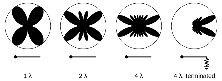
Extend a wire well beyond that, and different sections carry currents with different phases. Their fields reinforce in some directions and cancel in others, and the first three patterns in the figure below show how that changes with length.
On an unterminated long wire, the wave travels to the open far end and reflects back. Each traveling wave radiates mostly toward its own direction of travel, so the reflected wave adds a matching set of lobes toward the rear. A resistor from the far end to ground can absorb the wave instead, at the cost of the power it absorbs. A rhombic, four long wires in a diamond fed at one corner, can be terminated the same way at the opposite corner.
Key Information:
- An extended double Zepp antenna is a center-fed 1.25-wavelength dipole antenna.
- As the wire length of an unterminated long wire antenna is increased, additional lobes form with major lobes increasingly aligned with the axis of the antenna.
- Adding a terminating resistor to a rhombic or long-wire antenna changes the radiation pattern from bidirectional to unidirectional.
Reflections from the Ground #
A low dipole sends much of its signal upward, while a higher one favors the low angles that reach distant stations. The ground reflection introduced earlier in this chapter explains why. At a distant point, the reflected wave has traveled farther than the direct wave, by an amount that grows with both height and elevation angle. The reflection also reverses a horizontally polarized wave’s phase. Near the horizon, where the two paths are almost equal, the waves therefore cancel. They add where the extra path is half a wavelength, or 1½ wavelengths, since the reversal then puts them back in step. Over ideal ground, a dipole half a wavelength high first meets that condition at 30 degrees; one a full wavelength high meets it at about 15 degrees.

Height counts in wavelengths. A wire 10 meters high is half a wavelength up on 20 meters, but only one-eighth wavelength up on 80 meters. That’s why so many backyard 80-meter dipoles become “cloud warmers,” sending most of their signal nearly straight up: fine for nearby stations, less so for DX.
Over a long, uniform slope, the reflecting surface tilts, and the pattern tilts with it.
Vertical polarization reflects differently. Over ordinary soil, the reflected wave at low angles is weak and shifted in phase. It adds little to the direct wave near the horizon. Seawater conducts far better than soil, so its reflection stays strong and in step down to much lower angles.
Key Information:
- As a horizontally polarized antenna’s height above ground increases, the takeoff angle of the lowest elevation lobe decreases.
- Compared with flat ground, a horizontally polarized antenna mounted above a long slope has a main lobe takeoff angle that decreases in the downhill direction.
- Mounted over seawater versus soil, a vertically polarized antenna’s far-field elevation pattern shows increased radiation at low angles.
Ground Under a Vertical #
The ground does more than reflect. Under a ground-mounted vertical, it also carries the antenna’s return current, and ordinary soil conducts poorly. Radials give that current better paths near the base, where it is strongest, so less power heats the ground.
Key Information:
- Soil conductivity determines ground losses for a ground-mounted vertical antenna operating on HF.
- Installing a ground radial system improves the efficiency of a ground-mounted quarter-wave vertical antenna.
Less ground loss lowers the feed resistance toward the radiation resistance, about 36 Ω for a quarter-wave vertical. The SWR on 50-ohm line can then rise even as more power radiates. A higher SWR after adding radials may simply mean they are working.




 A half-wave dipole with an additional parallel wire connecting its two ends