

Section 6.7: Antenna Matching Methods #
Put an antenna tuner beside the radio and the transmitter sees a 50-ohm load, but the feed line beyond the tuner still carries the antenna’s mismatch. The radio is happy; the coax isn’t. A match made at the antenna clears the mismatch from the line. The methods here make that match with sections of transmission line or with connections to the radiating element itself.
A Quarter-Wave Transformer #
Suppose an antenna presents 100 ohms but the feed line is 50 ohms. A quarter-wave section of another line impedance can transform one into the other. For a lossless section and a resistive load ,
where is the matching section’s characteristic impedance. To connect a 100-ohm antenna to 50-ohm line, solve for the matching section:
The length must be one-quarter electrical wavelength at the operating frequency, including velocity factor. This arrangement is called a Q-section or quarter-wave transformer. Standard coax doesn’t come in 70.7 ohms, but 75-ohm cable, the kind behind many TVs, is common. A 75-ohm section transforms 100 ohms to , an SWR of only about 1.1:1 on the 50-ohm line.
Key Information: A 75-ohm transmission line is suitable for constructing a quarter-wave Q-section to match a 100-ohm feed point impedance to a 50-ohm transmission line.
Feeding Two Loads #
The same math lets one 50-ohm line feed two 50-ohm antennas. Connected directly in parallel, the two would present 25 ohms at their junction. A Wilkinson divider instead feeds each load through its own 70.7-ohm quarter-wave branch. Each branch turns its 50-ohm load into 100 ohms at the junction, where the two branches in parallel give 50 ohms. An isolation resistor reduces interaction between the output ports.
Key Information: A use for a Wilkinson divider is to divide power equally between two 50-ohm loads while maintaining 50-ohm input impedance.
Ideally, a 100-watt input supplies 50 watts to each load. Each output is 3 dB down because the power is split, not lost as heat.
The Gamma Connection #
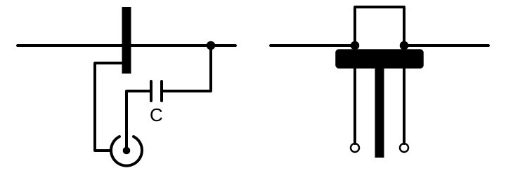
Both methods above connect to a feed point. A Yagi’s driven element is often a continuous tube bolted straight to a metal boom, with no break at its center to serve as one. Coax can still feed it. The shield connects at the element’s center, and the center conductor runs out along a parallel rod, the arm, to a point off center. How far out that point sits sets the resistance the coax sees. The arm and the part of the element beside it also form a short line, shorted at the far end. Like the shorted stubs in Section 6.3, it acts as an inductor, so a capacitor goes in series with the arm.
Because this feed arrangement does not require a center break in the radiator, it can work with an electrically grounded structure. On a grounded tower used as a vertical radiator, the arm attaches partway up the tower. The coax shield connects to the grounded base and ground system; the center conductor feeds the arm through the matching capacitor. Feeding RF alongside the direct ground connection this way is called shunt feeding.
Key Information:
- A gamma match matches coaxial cable to an antenna by connecting the shield to the center of the antenna and the conductor a fraction of a wavelength to one side.
- The purpose of the series capacitor in a gamma match is to cancel unwanted inductive reactance.
- A gamma match is used to shunt feed a grounded tower at its base.
The Hairpin Connection #
With a split driven element, a beta or hairpin match uses the element itself as part of the matching network. The hairpin, a short length of line shorted at its far end, sits across the feed point and acts as an inductor. A Yagi’s driven element often presents well below 50 ohms. Like the matching networks in Section 3.1, the hairpin works with a reactance of the opposite kind in the element. Together they cancel the reactance and raise that low resistance to the value the line needs. Because the element is split and fed across its center gap, bonding both halves directly to a metal boom would short that gap.
Key Information:
- The beta or hairpin matching system for Yagi antennas requires the driven element to be insulated from the boom.
- A beta or hairpin matching system requires a capacitive Yagi driven element feed point impedance, with the driven element electrically shorter than 1/2 wavelength.
Stubs in Parallel #
The hairpin is itself a shorted stub placed right at the feed point. A stub can also sit some distance down the feed line, connected in parallel with it. Moving along a mismatched line changes what it presents, and at certain points, adding the right reactance in parallel leaves exactly the line’s characteristic impedance. A shorted or open stub at one of those points supplies that inductive or capacitive reactance. The stub’s length sets its reactance; its position sets what it must correct.
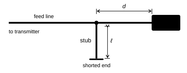
Key Information: A stub match uses a short length of transmission line connected in parallel with the feed line at or near the feed point.




 75 ohms