

Section 9.2: Improving Reception #
You turn up the gain, the speaker gets louder, and the call sign stays unreadable. More sound has not bought you more information. Better copy starts with knowing how much signal to expect. After that, the control that helps depends on the problem: noise, a nearby station, or a strong signal overloading the input.
Following the Signal Level #
That expectation comes from a link budget, which you probably studied for the General exam. Start with the transmit power, add antenna gains, and subtract losses along the path. Power levels use dBm, referenced to one milliwatt. Gains and losses use dB, and dBi measures antenna gain against an isotropic antenna.
For a 10 W transmitter, start at +40 dBm: 10 W is 10,000 mW, 40 dB above 1 mW. Add the transmitting antenna’s 6 dBi gain and the receiving antenna’s 3 dBi gain, then subtract 100 dB of path loss:
Key Information: A transmit power of 10 W (+40 dBm), transmit antenna gain of 6 dBi, receive antenna gain of 3 dBi, and path loss of 100 dB produce a received signal level of −51 dBm.
The link margin tells how far the received level sits above the level the link requires. In a second example, the two antennas provide a combined 10 dB of gain. Cable loss is 3 dB and path loss is 136 dB:
The receiver’s minimum discernible signal, or MDS, is −103 dBm. At MDS, the signal’s power only equals the receiver’s noise (Section 5.3). This link needs a 6 dB signal-to-noise ratio, so the required level is 6 dB higher: dBm. The received signal exceeds it by
Key Information: For +40 dBm transmit power, 10 dBi system antenna gain, 3 dB cable loss, 136 dB path loss, −103 dBm receiver MDS, and a required 6 dB signal-to-noise ratio, the link margin is +8 dB.
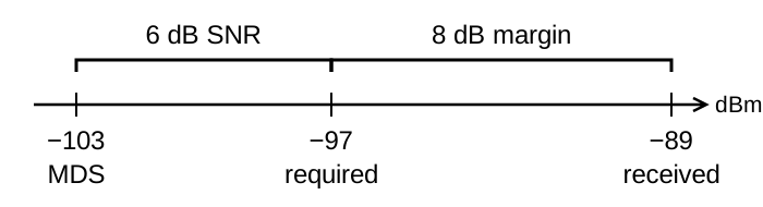
Read that +8 dB as an allowance for extra loss. If the path gets 5 dB worse, 3 dB of margin remains. If it gets 9 dB worse, the link falls 1 dB short. Turning up the gain can’t make that up, because it raises the noise along with the signal.
Admit Only What You Need #
Whether a signal at that level is readable also depends on what arrives with it. Noise power grows with bandwidth, and a wider passband admits more neighboring signals. A passband narrower than the signal itself, though, cuts the signal you are trying to copy. CW needs a much narrower passband than SSB.
Key Information: A choice of receiver bandwidths lets you match the modulation bandwidth, maximizing signal-to-noise ratio and minimizing interference.
The position of a filter matters as much as its width. The roofing filter from Section 5.4 protects the stages after the mixer. A strong signal well outside the band can overload the first active stage before it gets that far, and a later IF filter cannot undo overload that has already happened. A preselector is a tuned filter ahead of that stage.
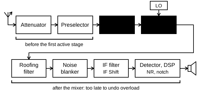
Key Information:
- A front-end filter or preselector can eliminate interference from strong out-of-band signals.
- A preselector increases rejection of signals outside the band being received.
Suppose a nearby station sits just inside one edge of your receive passband. The IF Shift control slides the IF filter’s passband while the receiver stays tuned to the same station. The moving edge can also trim the wanted signal, so judge the setting by whether you can copy the contact.
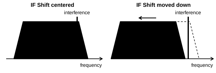
Key Information: The receiver IF Shift control reduces interference from stations transmitting on adjacent frequencies.
When Less Input Helps #
A preselector cannot reject a strong signal inside the band you are receiving. That signal can push the first RF stage toward compression, so the stage gives every signal less gain: the desensitization described in Section 5.4. Attenuation ahead of that stage keeps it in its linear range, but it also weakens the wanted signal.
Whether that hurts copy depends on which noise is stronger: the noise arriving from the antenna or the receiver’s own. Attenuation lowers the signal and the antenna’s noise together. As long as both stay above the receiver’s internal noise, their ratio barely changes. On the lower HF bands, the atmosphere supplies most of the noise from the antenna.
Key Information:
- Inserting attenuation before the first RF stage reduces the likelihood of receiver desensitization.
- On the lower HF bands, attenuation can reduce overload with little or no effect on signal-to-noise ratio because atmospheric noise is generally greater than internally generated noise even after attenuation.
Compare reception with and without attenuation, and keep it only when copy improves.
Noise Controls Have Side Effects #
The noise pattern determines which processing is useful. Digital noise reduction keeps sound that follows a pattern from moment to moment, as speech does, and suppresses sound that looks random. White noise contributes roughly equal power in equal-width frequency ranges. A noise blanker instead watches for brief, large pulses and shuts off the signal path for those instants. An automatic notch hunts for steady tones and removes them, and a CW note is a steady tone too.
The blanker works ahead of the narrow IF filter, where strong signals near your frequency are still present. Blanking chops those signals too, and chopping a strong signal creates new frequency components. Some of them land in your passband.
Key Information:
- Digital noise reduction can often reduce broadband white noise, ignition noise, and power line noise.
- A noise blanker removes impulse noise.
- An automatic notch filter used while receiving CW may remove the CW signal along with the interfering carrier.
- A noise blanker can distort strong signals, making them appear to cause spurious emissions.
If a station seems to splatter only when your noise blanker is on, check the receiver setting before blaming the transmitter.
Receiver controls may make a noisy band usable. When the noise comes from equipment nearby, finding its source can give a better result than processing it after it arrives.




 -51 dBm