

Section 9.4: Meters, Scopes, and Counters #
Voltmeters have a high input impedance so measuring a circuit disturbs it as little as possible. Little is not nothing. Each instrument in this section can change or misread what it measures. A meter loads the circuit or misjudges a waveform, a scope’s probe and sampling can distort the trace, and a counter is only as good as its clock.
A Meter Draws Current Too #
To estimate how much an analog voltmeter loads a circuit, find its input resistance on the selected range. Its ohms-per-volt rating converts range to resistance.
Key Information: A voltmeter’s full-scale reading multiplied by its ohms-per-volt rating gives its input impedance.
The needle’s position doesn’t enter into it; the range switch sets the meter’s resistance. A 20,000 Ω/V meter on its 10 V range presents Ω, or 200 kΩ. On the 50 V range, it presents 1 MΩ. The lower range draws more current, and across a high-resistance source that extra load can pull down the voltage you were trying to measure.
Waveform shape matters too. An average-responding AC meter may scale its reading to show the correct RMS value for a sine wave. A distorted waveform breaks that assumption. A true-RMS meter calculates the heating-equivalent value from the waveform itself, within its rated frequency range and peak level.
Key Information: A true-RMS calculating meter measures RMS voltage for both sinusoidal and non-sinusoidal signals.
Make the Probe Behave #
Before trusting a waveform’s shape, check that the probe itself is not rounding or exaggerating its transitions. A typical ×10 passive probe forms a voltage divider with the scope input. Its compensation adjustment balances capacitance so fast changes and steady levels receive the same attenuation. A square wave has both fast edges and steady levels, so the scope’s square-wave calibration output shows any imbalance at once. Too little compensation rounds the rising edge; too much produces an overshoot before the top settles.
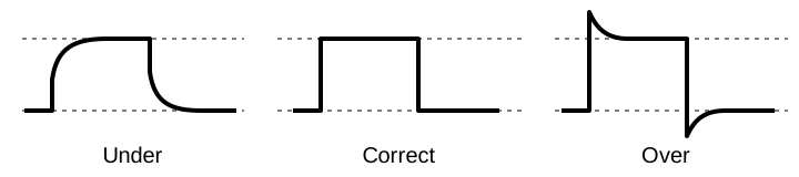
The probe’s ground lead can distort the trace too. A long one adds inductance and forms a pickup loop, adding ringing that belongs to the probe setup rather than the circuit.
Key Information:
- Compensate an oscilloscope probe by displaying a square wave and adjusting the probe until the horizontal portions are as nearly flat as possible.
- Good practice when using an oscilloscope probe is to minimize the length of the probe’s ground connection.
On an ordinary bench scope, the probe’s ground clip connects to protective earth through the power cord. Clipping it to a point that isn’t at ground potential creates a short circuit through the scope.
Suppose you’re checking the low-voltage output of a linear power supply. AC coupling, a scope input setting that blocks the steady DC level, lets you magnify the small ripple. A scope’s trigger sets the starting point for each trace. Line triggering synchronizes that start with the AC power cycle. Ripple repeats at the line frequency or twice it, so each new trace lands on the last and the ripple stands still.
Key Information: Line trigger mode is most effective for measuring a linear power supply’s output ripple.
A Plausible but False Trace #
A well-compensated probe can still feed a misleading display. A digital oscilloscope’s analog-to-digital converter takes samples at separate instants, and Section 5.1 showed that the rate must be at least twice the highest frequency present. Below that rate, a fast input can produce the same samples as a much slower wave. The sampling clock also runs independently of the trigger, so where the samples fall on the input shifts from one sweep to the next.
Key Information:
- The analog-to-digital converter’s sampling rate limits the highest frequency that a digital oscilloscope can display accurately.
- Aliasing can display a false, jittery low-frequency version of the waveform.
A trace that changes unexpectedly when you change the time scale deserves suspicion. Check the actual sample rate as well as the scope’s analog bandwidth.
Counting Against a Clock #
A frequency counter, like a digital multimeter, can show many digits and still be wrong. It counts input cycles against its time base, an internal timing reference. A fast or slow reference shifts the reported frequency by the same fraction. A time base off by one part per million makes a 146 MHz signal read 146 Hz high or low, however many digits the display shows.
The input frequency may also exceed the counter’s range. With a divide-by-10 prescaler ahead of the counter, a 450 MHz signal reaches it as 45 MHz; the final result must include the factor of ten.
Key Information:
- Time base accuracy is the factor that most affects a frequency counter’s accuracy.
- A prescaler reduces the signal frequency to within a frequency counter’s operating range.




 The full scale reading of the voltmeter multiplied by its ohms per volt rating is the input impedance of the voltmeter