

Section 9.5: Measuring RF Networks #
An SWR meter answers one question about a feed line: how well does the load match it? Other instruments answer it too. They differ in what else they reveal: the power reaching the load, the load’s resistance and reactance, or how much signal passes through a device at each frequency.
Power Going Each Way #
A directional wattmeter reads the power traveling toward the load and the power reflected back. Their ratio sets the SWR, and their difference is the net power flowing toward the load at the measurement point. For a meter placed at a terminating load, subtract the reflected reading from the forward reading:
Key Information: A directional power meter reading 100 W forward and 25 W reflected indicates that the terminating load absorbs 75 W.
If a lossy line lies between the meter and the load, account for that loss before treating the result as power delivered to the antenna.
A simple SWR bridge is the circuit inside a basic SWR meter. It compares forward and reflected signals and shows only the mismatch. On many basic meters, you first set the forward reading to full scale, then switch to reflected to read the SWR. An antenna analyzer sweeps the antenna system with its own small test signal and shows resistance and reactance as well.
Key Information: An antenna analyzer’s advantage over an SWR bridge is that it computes SWR and impedance automatically.
You still choose the wire length or tuning setting, but the readings show what each adjustment changed. Low SWR alone does not prove resonance or good radiation efficiency. Use the impedance reading to see whether reactance is near zero, and remember the losses discussed in Chapter 6.
Two Ports, Two Different Questions #
An antenna has one connection to measure, but a filter has two. Its input match tells you how much signal it reflects, not how much gets through. The rest either passes through or is lost inside the filter. A vector network analyzer, or VNA, measures at both test connections, called ports. It measures phase as well as magnitude, hence the “vector” in its name. Connect the filter’s input to port 1 and output to port 2. The filter is the DUT, or device under test.
The VNA describes traveling signals with scattering parameters, usually shortened to S parameters. The first subscript says where the VNA measures the response; the second says which port it drives. Thus reads “response at port 2 from a signal applied at port 1.” Read the subscripts in that order even though the test signal travels from 1 to 2.
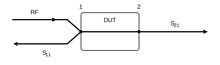
What returns to port 1, compared with what left it, is the reflection coefficient from Section 6.3, phase included. Driving port 2 instead gives the output-port reflection, , and the reverse path, . At either port, a reflection’s size and phase together reveal the resistance and reactance that produced it.
For the input match, return loss expresses the forward-to-reflected power ratio in decibels: a larger positive value means less reflection. VSWR is the voltage standing-wave ratio. Both describe reflection, whereas forward gain describes transmission.
Key Information:
- S-parameter subscripts represent the port or ports at which measurements are made.
- represents the input-port reflection coefficient, from which input return loss and VSWR can be found.
- is equivalent to forward gain.
- A VNA can measure input impedance, output impedance, and reflection coefficient.
- A directional wattmeter, vector network analyzer, or antenna analyzer can measure SWR.
Calibrate, Then Sweep #
The cables and connectors between the VNA and the filter add their own response. Calibrating at the point where the filter connects lets the analyzer remove those errors instead of blaming them on the filter. Calibration uses standards with known reflections. A short reflects with one phase, an open with the opposite phase, and a matched load reflects almost nothing.
Key Information: The three test loads used to calibrate an RF VNA are a short circuit, an open circuit, and a 50-ohm load.
Connect the standards at the end of the test cable if that is where the device will attach. A full two-port calibration also uses a through connection between ports. Follow the instrument’s procedure and keep the same cable arrangement after calibration.
Now connect a filter between ports 1 and 2 and sweep frequency. The plot shows the passband, loss within it, and rejection outside it. The plot shows the match across the passband. Outside the passband, climbs toward full reflection, because a typical filter rejects a signal mostly by reflecting it back toward the source.
Key Information: A two-port VNA can measure filter frequency response.
For a suitable single-resonance response, you can also apply the relationship from Section 2.4. A response centered on 10 MHz with 100 kHz between its half-power points, 3 dB below the peak, has , using kilohertz for both numbers.
A Feed Line as a Test Object #
An antenna analyzer’s sweep can reveal a cable’s electrical length as well as its impedance. A shorted cable looks like an open circuit at the frequency where it is an electrical quarter wavelength long, as Section 6.3 showed. Suppose a shorted 10 m cable looks open at 4.95 MHz. A free-space quarter wave there is m, so the velocity factor is . With the velocity factor known instead, the same measurement gives the length. For a tuned circuit, look for the resonance behavior from Chapter 2: inductive and capacitive effects cancel, leaving a resistive impedance.
Key Information: An antenna analyzer can measure velocity factor, cable length, and the resonant frequency of a tuned circuit.
Disconnect the transmitter before connecting an analyzer. Its measurement port is built for a small test signal, not transmitter power. Key up into it by mistake, and it may never measure anything again.




 75 watts