

Section 9.6: Checking Transmitter Output #
On a waterfall display, an overdriven data signal grows extra lines beside its tones. The waterfall shows them because it spreads signals out by frequency. A wattmeter can’t. It adds wanted and unwanted power together, so full output says nothing about how clean the signal is. A spectrum analyzer does for a transmitter’s RF output what the waterfall does for received audio.
Key Information:
- A spectrum analyzer displays signal amplitude on the vertical axis and frequency on the horizontal axis.
- A spectrum analyzer can display spurious signals and intermodulation distortion products from an SSB transmitter.
Give Distortion a Recognizable Pattern #
A two-tone linearity test swaps ever-changing speech for a steady signal. Unwanted products then form a repeatable pattern. The test uses two audio tones, chosen so that neither is a whole-number multiple of the other. That keeps ordinary harmonics separate from mixing products. A linear transmitter turns the two audio tones into just two RF tones, and nonlinearity adds more products at predictable frequencies.
Key Information: Measure SSB transmitter intermodulation distortion by modulating it with two AF signals at non-harmonically related frequencies and observing the RF output with a spectrum analyzer.
The products closest to the pair are the third-order products from Section 5.4. Around RF tones at and , they fall at and , one tone-spacing outside the intended pair.
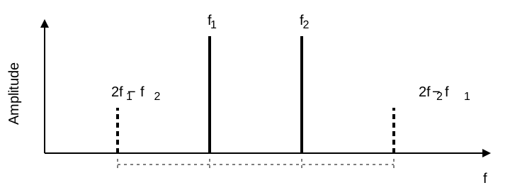
For RF tones at 7.101 and 7.102 MHz, those products land at 7.100 and 7.103 MHz. Reducing drive should reduce products caused by overdriving a stage.
Use a suitable dummy load and a correctly rated attenuator or sampling coupler. The analyzer receives a small sample of the output, not the transmitter’s full power. The analyzer itself must also stay below overload, or its own distortion can spoil the test.
Set Digital Audio for a Clean Signal #
The extra waterfall lines beside an overdriven data signal are products of the same kind. AFSK sends audio tones through the SSB transmitter. Too much audio drives a stage beyond its linear range, where extra drive creates unwanted frequencies instead of more clean output. Output power alone therefore can’t tell you the right audio level. Scan a busy FT8 waterfall, and you’ll often spot the result: a signal trailing extra lines because its operator ran the audio too high.
Key Information:
- Excessive transmit audio levels are a common cause of AFSK overmodulation.
- Intermodulation distortion, or IMD, evaluates AFSK distortion caused by excessive input audio levels.
Start with low audio and keep speech processing off. Then raise the level while watching the signal’s quality, not just its power.
When PSK31 has no text to send, it reverses phase continuously, using the smooth reversals described in Section 4.4. On a spectrum display that idle signal appears as two steady tones about 31 Hz apart: a built-in two-tone test. The IMD reading compares the unwanted products with those tones. Its minus sign says the products lie below the tones, so a more negative value means smaller products.
Key Information: An acceptable maximum IMD level for an idling PSK signal is −30 dB.
At −30 dB, the measured distortion power is one thousandth of its reference power; at −20 dB, it is one hundredth, ten times as much. A clean signal decodes reliably and leaves room for the next contact beside you.




 Signal amplitude and frequency